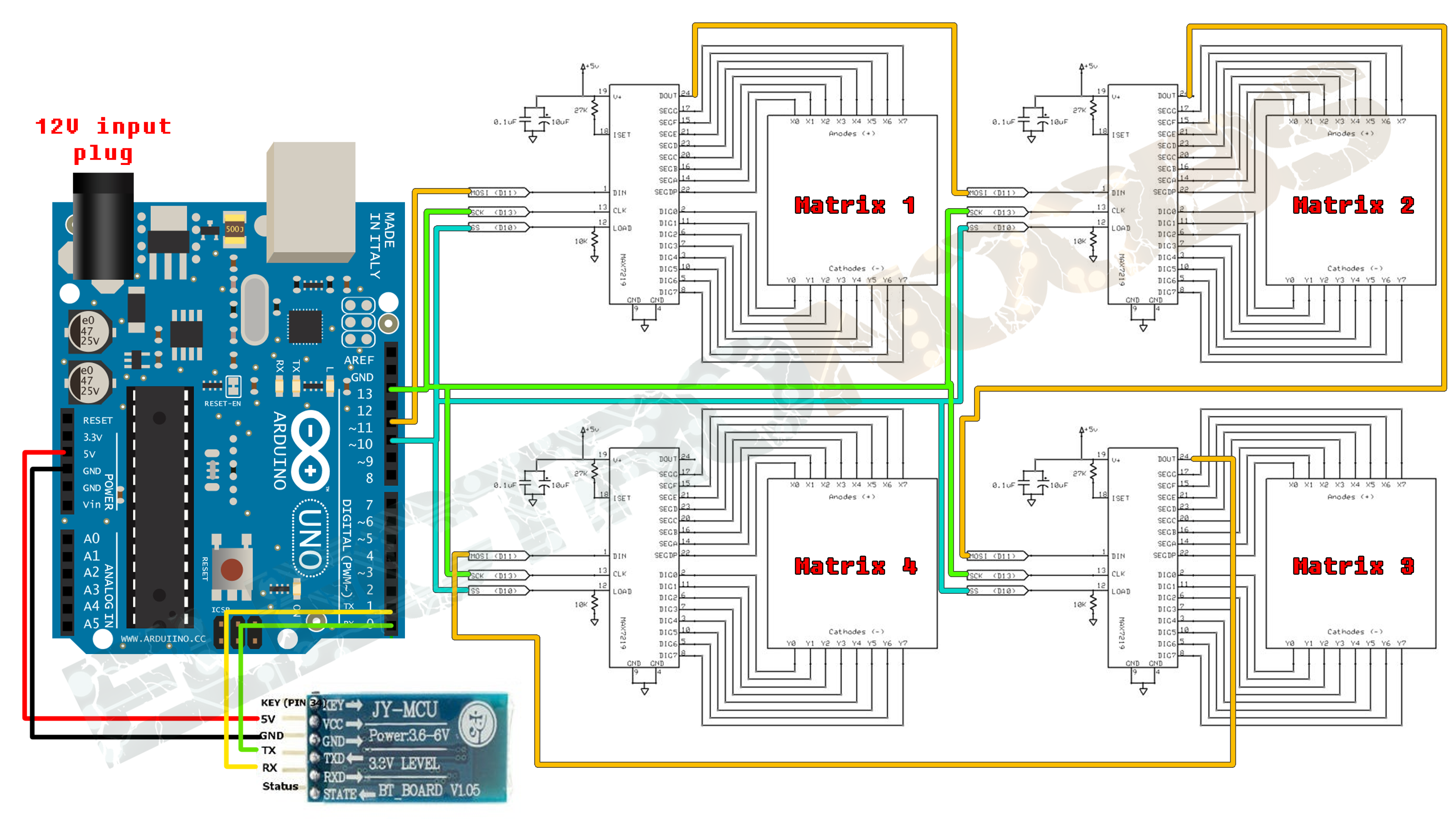

- #Arduino led matrix max7219 serial
- #Arduino led matrix max7219 driver
- #Arduino led matrix max7219 code
We are including SPI.h as we are using SPI communication protocol between the two devices. Including Librariesįirstly, we will include all the necessary libraries for this project.
#Arduino led matrix max7219 code
In this part we will discuss how the code works. MD_Parola Display = MD_Parola(HARDWARE_TYPE, CS_PIN, MAX_DEVICES) #define HARDWARE_TYPE MD_MAX72XX::GENERIC_HW #define HARDWARE_TYPE MD_MAX72XX::FC16_HW Uncomment according to your hardware type MAX7219 LED Dot Matrix Module Interfacing with ESP8266
#Arduino led matrix max7219 serial

The reason for connecting all rows and columns together is to save the required number of pins to control each LED dot. Each LED is referred to as a dot.įor making an 8×8 dot matrix all the anodes terminals are connected together in rows R1 to R8, similarly, the cathodes are connected together in columns C1 to C8. Each LED is addressed by its row and column number. The typical 8×8 LED matrix is shown below which comprises of 64 LEDs, 8 for each row and column. LED dot matrices are available in various dimensions (7×5,8×8, 7×15, etc).
#Arduino led matrix max7219 driver
MAX7219 8-Digit LED Display Driver LED Dot Matrix These are the FC-16 module and the generic module. There are two types of modules generally available. MAX7219 LED Dot matrix display is one of the popular ones available in the market and used by students, electronics hobbyists, and especially in industrial display applications.

We have similar guides with ESP32 and Arduino: These will include displaying and scrolling text on the dot matrix. Through this tutorial, we will familiarize you with the MAX7219 dot matrix display and program ESP8266 to show various demonstrations of displaying texts. It is an LED array used to display various types of texts, symbols, and images in the form of dots which consists of LEDs. Firstly, we will look into the introduction, pinout of MAX7219 LED dot matrix display module.

In this tutorial, we will learn to interface MAX7219 LED Dot matrix display with ESP8266 NodeMCU.


 0 kommentar(er)
